Product Overview
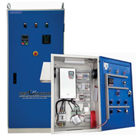
The Venema VCP-VSD Series control panels are designed to regulate the speed of three-phase motors from 0.4 kW to 3000 kW using advanced Variable Frequency Drive (VFD) technology. They ensure precise control of pressure and flow while significantly improving energy efficiency and equipment lifespan.
Built with industrial-grade components and engineered for reliability, these panels are suitable for irrigation systems, water-supply stations, HVAC systems, and process automation where smooth acceleration, torque management, and overload protection are essential.
Technical Specification
Power Range |
Voltage |
Freq. |
Enclosure |
Protection Degree |
Operation Mode |
|---|---|---|---|---|---|
|
0.4 – 3000 kW |
3 ~ 400 V ± 10% |
50 Hz |
Metal |
IP20 – IP65 |
Manual / Automatic |
|
0.4 – 3000 kW |
3 ~ 400 V ± 10% |
50 Hz |
Metal |
IP20 – IP65 |
Integrated |
Standar Features
Standar Panel Components
Components |
Spesification / Function |
|---|---|
|
Mini Circuit Breaker (MCB) |
Protection for control circuit |
|
Moulded Case Circuit Breaker (MCCB) |
Main protection for motor circuit |
|
Trafo (Control Transformer) |
Auxiliary supply for low-voltage control |
|
Inverter (VFD) |
Monitors current and protects against faults |
|
Motor Relay 3-Phase |
Temperature protection for motor windings |
|
Phase Failure Relay |
Detects incorrect phase sequence / loss |
|
Pressure Transmitter |
Enables automatic pressure control |
|
Digital VAF / Power Meter |
Displays voltage, amperage, frequency |
|
Auto-Manual Selector |
Operation mode control |
|
Pilot Lamps (Run / Fault) |
Visual indicators for operation & faults |
|
Push Buttons (Start / Stop) |
Manual control interface |
|
Water Level Control (WLC) |
Automatic tank-based motor control |
|
HZ Meter |
Frequency display for monitoring |
|
Terminal Blocks & Cable Ducts |
Organized internal wiring system |
Optional Components
Components |
Description |
|---|---|
|
Surge Arrester (3-Pole 40 kA) |
Protection against voltage spikes |
|
Analog Pressure / Flow Sensor |
PID-controlled analog feedback option |
|
Remote Communication Module |
Modbus / SCADA connectivity |
|
Additional Cooling Fan |
For high-power continuous operation |
|
Timer + Socket |
Programmable timing and delay functions |
|
Power Factor Correction Kit |
Integrated capacitor bank (on request) |
Safety and Function Summary
Protection Function |
Purpose |
|---|---|
|
Overload / MCCB |
Prevents thermal and overcurrent faults |
|
Phase Failure Relay |
Prevents start under incorrect phase order |
|
Inverter Protection |
Protects drive from overvoltage / short-circuit |
|
Pressure Transmitter |
Maintains stable system pressure |
|
Water Level Control |
Automatic lling / draining operation |
|
Surge Arrester (Optional) |
Protects electronics from transients |
Operating Conditions
- Ambient temperature : −5 °C to +40 °C
- Relative humidity : ≤ 80 % (at 20 °C)
- Installation altitude : ≤ 1000 m a.s.l.
- Environment : Clean, dry, non-corrosive, indoor
Example Application
Perfect for industrial pump systems, deep-well and booster stations, VAC
installations, and process automation networks where eficiency, flexibility, and protection are critical.