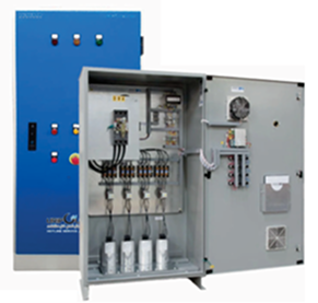
Product Overview
The Venema VCP-CBK Series capacitor bank panels are engineered to improve electrical system efficiency by automatically correcting power factor and minimizing reactive energy losses.
Designed for both automatic step control and fixed configurations, these panels optimize energy usage, reduce penalty charges, and stabilize voltage within the network.
Each unit is assembled using high-quality contactors, fuses, capacitors, and control relays to ensure long service life and consistent performance under tropical operating conditions.
The system can be installed as a stand-alone bank or integrated within existing distribution panels.
Technical Specification
Current Range |
Enclosure |
Protection Degree |
Operation Mode |
|---|---|---|---|
|
100A – 3200A |
Metal |
IP20 – IP65 |
Manual / Automatic |
Construction & Design Features
The Capacitor Bank panels are designed for safety, accessibility, and low maintenance.
All units are built in rigid, powder-coated metal enclosures with adequate ventilation to prevent overheating during capacitor switching operations.
Key construction features include:
- Metal enclosure with IP54 / IP65 protection rating
- Ventilation louvers or fans for heat dissipation
- Copper busbar system with fully insulated terminals
- Step-type automatic controller for reactive power management
- Heavy-duty contactors and fuses for each capacitor step
- Built-in discharge resistors to safely discharge capacitors after deenergization
- Top or bottom cable entry options
Applications
- Industrial and commercial power distribution systems
- Irrigation pump stations and water treatment facilities
- Manufacturing plants with high inductive load demand
- Commercial buildings and large electrical networks
Standar Features
Optional Features
- Detuned reactor system for harmonic filtering
- Manual control override for maintenance and testing
- Remote communication interface (Modbus / RS-485)
- Alarm and trip signaling output
- Temperature and ventilation control system
- Outdoor-rated or stainless-steel enclosure
- Integrated energy meterfor power monitoring
Operation Principle
The capacitor bank panel continuously monitors the system power factor through a microprocessor-based controller.
When the power factor drops below the preset level, the controller automatically switches the required number of capacitor steps to maintain the desired level.
Upon reduced load demand, unnecessary steps are disconnected to prevent
over-correction and extend component life.
Operating Conditions
- Ambient temperature: −5 °C to +40 °C
- Relative humidity: ≤ 80 % (at 20 °C)
- Installation altitude: ≤ 1000 m above sea level
- Environment: Dry, clean, and ventilated indoor areas
Customization
All Venema capacitor bank panels are custom-engineered to suit the client’s load profile, target power factor, and site conditions.
Capacitor capacity, number of steps, enclosure size, and ventilation requirements are determined based on detailed system analysis by Venema’s engineering team.
Example Application
Ideal for industrial or agricultural electrical systems with high inductive load, such as motor-driven pumps, compressors, and conveyors, where maintaining an
optimum power factor is essential for energy eficiency and voltage stability.